![]()
![]()
Top > Releases ・ Announcements > Press Releases > Status of TEPCO's Nuclear Power Stations after theTohoku-Chihou-Taiheiyou-Oki Earthquake > 2013 > Status of TEPCO's Nuclear Power Stations after the Tohoku-Chihou-Taiheiyou-Oki Earthquake (Daily Report as of 3:00 PM on September 4)
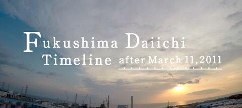
Due to the Tohoku-Chihou-Taiheiyou-Oki Earthquake which occurred on March 11, 2011, TEPCO's facilities including our nuclear power stations have been severely damaged. We deeply apologize for the anxiety and inconvenience caused.
With regard to the accident at Fukushima Daiichi Nuclear Power Station, on April 17, 2011, we have compiled the roadmap towards restoration from the accident and on July 19 we accomplished the Step1 target "Radiation dose is in steady decline". Then on December 16 we confirmed the accomplishment of the Step 2 target "Release of radioactive materials is under control and radiation doses are being significantly held down".
In addition, on December 21, 2011, we have compiled the "Mid-to-long-Term Roadmap toward the Decommissioning of Fukushima Daiichi Nuclear Power Units 1-4, TEPCO".
In addition to the maintenance of the plant's stable condition, we will implement Mid-to-Long Term countermeasures towards the decommissioning of Fukushima Daiichi Nuclear Power Units 1-4 to enable evacuees to return to their homes as soon as possible and reduce the anxiety of the people in Fukushima and the whole nation as soon as possible.
Below is the status of TEPCO's Fukushima Daiichi Nuclear Power Station.
* The updates are underlined.
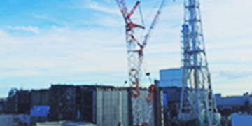
[Fukushima Daiichi Nuclear Power Station]
・ Unit 1 to 4: Abolishment (April 19, 2012)
・ Unit 5 to 6: Outage due to regular inspections before the earthquake
- On September 3, sampling at the charcoal filter and the particulate filter of the Unit 1 PCV gas control system, and dust sampling in the upper part of Unit 1 Reactor Building using the exhaust gas filtering facilities of the Unit 1 Reactor Building cover were conducted.
- Contaminated water transfer from the underground reservoirs was all completed as of July 1. However, we are continuing to take measures to prevent the expansion of contaminated water, and to conduct sampling activities.
<Measures to prevent the expansion of contaminated water>
・ Since the decreases of all-β radioactivity densities in the leakage detection holes (at the northeast side of the underground reservoir No.1, the northeast side of the underground reservoir No.2, and the southwest side of the underground reservoir No.3) have been slow, operations to dilute the underground reservoirs No.1-No.3 by transferring filtered water or desalination-system (RO) treated water (the all-β radioactivity density: approx. 1×101Bq/cm3) into these reservoirs have been conducted as appropriate.
[Recent dilution operations]
Underground reservoir No.1 (since June 19): On August 3, approx. 60m3 of filtered water was injected.
Underground reservoir No.2 (since June 27): On August 1, approx. 60m3 of filtered water was injected.
Underground reservoir No.3 (since July 24): On August 12, approx. 107m3 of water in the drain hole (northeast) of this underground reservoir was injected.
・ On September 2 and 3, leaked water in the leakage detection holes at the underground reservoirs No.1-No.3 was transferred to the temporary aboveground tank, and leaked water in the drain holes at the underground reservoirs No.1 and No.2 was transferred into these underground reservoirs.
<Sampling>
On September 3, sampling was performed in the drain holes of the underground reservoirs No.1-No.7 (14 locations), the leakage detection holes of the underground reservoirs No.1-No.4 and No.6 (sample could not be collected at 2 out of 10 locations), the observation holes of the underground reservoirs (22 locations), the groundwater bypass investigation holes a-c (sample could not be collected at 1 out of 3 locations), the groundwater bypass pump wells No.1-No.4, and the observation holes on the sea side (1)-(4). No significant change was found in the analysis results compared to the analysis results from the sampling performed previously (on August 27 in the observation holes on the sea side (1)-(4), and on September 2 in the other locations).
Further, analysis for tritium was performed on water sampled on August 26 and 27 in the groundwater bypass (investigation holes a-c and pump wells No.1-No.4; sample could not be collected at 1 investigation hole out of 3 investigation holes) and the observation holes on the sea side (1)-(8). As a result, no significant change was found compared to the previous analysis results (from the sampling on August 19 in the observation holes on the sea side (5)-(8), and on August 20 in the other locations).
- At around 9:50 AM on August 19, a TEPCO employee on patrol found water leaking from a drain valve of a tank dike in the H4 area in the power station. Later, the drain valve was closed. No significant change has been found in the monitoring post readings. As a result of confirmation on the site conditions, a puddle of approx. 1-2cm was found inside the dike, and puddles of approx. 3m×3m×1cm and approx. 0.5m×6m×1cm were found outside of the drain valve of the dike. There is no trace of water having flowed into a public drainage ditch, etc. from the puddles found outside of the drain valve of the dike. Therefore, we consider that the water has not flowed out into the sea.
At 2:28 PM on August 19, we determined that this incident corresponds to "a case when nuclear fuel material (not in the form of gas) or the like has leaked within an area controlled by the company due to an unpredictable event such as a failure of a nuclear reactor facility for power generation" as per Article 18, item 12 of the regulations concerning the operational safety and the protection of specified nuclear fuel material at the TEPCO's Fukushima Daiichi NPS nuclear reactor facilities. The reasons for the determination are as follows:
・ Although we have not yet been able to identify the source of contaminated water, water accumulated inside the dike around a tank containing contaminated water has leaked outside the dike through the drain valve.
・ It cannot be denied that water stored in a tank has leaked from the tank.
・ High β ray and γ ray densities were detected in the puddle of water having leaked outside the dike.
We found water spread at the bottom level of tanks near the tank No.5 (H4-I-5) in the area. Therefore, we checked the water level of this tank, and found out that the current water level has fallen by approx. 3m than the normal level. Note that the amount of water corresponding to this approx. 3m fall in water level is approx. 300m3. With regards to water considered to have leaked, we started collecting the water remaining inside the dike and already collected some of the water. However, since the water seems to have flowed out of the dike through the drain valve, we will collect soil in the surrounding area and continue to conduct an investigation to find out the range reached by the water. Later, we found streaky traces of flows on the wall surface of a drainage channel located east of the H4 area tanks. In response, we measured surface dose equivalent rates at this location, and the maximum rate was 6.0mSv/h (γ and β rays (70μm dose equivalent rate)). As this information indicates the possibility that contaminated earth and sand, etc. may have flowed into the drainage channel, we are planning to conduct a detailed investigation and evaluation concerning these traces. Incidentally, we confirmed that no water was flowing on the surface of the ground near the above drainage channel at the time when water leaking this time was found.
At 9:55 PM on August 20, we started transferring water stored in the tank No.5 in the group I in the H4 area and water collected in a temporary tank (water accumulated inside the dike) into the tank No.10 in the same area. Water transfer was completed on August 22.
From around 11:00 AM to around 3:00 PM on August 22, we conducted full inspections (appearance inspections and dose measurement) on the flanged tanks in the other areas, which are of the same type as the tank from which water has leaked. Neither leak nor puddle was found by the appearance inspections on the tanks and the drain valves. However, 2 locations locally showing high dose rates were found around the H3 area tanks. The surfaces of these locations were dry, and we confirmed that there has been no water having flowed into the inside of the dike or the outside of the dike. We also confirmed that the water levels of these tanks remain unchanged after they received water.
[High dose rate locations, the surface dose equivalent rates at these locations (γ and β rays (70μm dose equivalent rate)), and tank water levels]
・ Near the bottom flange of the tank No.4 in the group B in the H3 area: 100mSv/h and approx. 97% of the full water level
・ Near the bottom flange of the tank No.10 in the group A in the H3 area: 70mSv/h and approx. 95% of the full water level
No locations around the other tanks and drain valves showed high dose rates.
Additionally, we conducted full inspections (visual appearance inspections and water level confirmation) on the flanged tanks that are in use for storage of accumulated water from Units 5 and 6. The inspections were completed on August 26 and showed no abnormality.
During our inspection of Tank No.5 in Group I in the H4 area from which water has leaked, we found out the following:
・ 3 tanks including this tank (Tank No.5 in Group I, Tank No.10 in Group I, and Tank No.3 in Group II in the H4 area) were initially installed in the H1 area.
・ Ground subsidence occurred in the H1 area at the foundations on which these tanks had been placed, and these tanks were planned to be installed in the H2 area, but actually, have been placed in the H4 area despite our plan.
Although it is still unclear whether there is a causal relationship between the water leaking of Tank No.5 and the tank's having experienced ground subsidence occurred in the H1 area at the foundation on which it had been placed, we conducted water transfer from inside Tank No.3 in Group II in the H4 area to Tank No.10 in Group B in the H4 area.
<The latest transfer operation>
At 7:44 AM on September 2, water transfer was restarted. At 11:03 AM on the same day, water transfer was suspended due to the implementation of rainfall countermeasures.
During a patrol on August 31, we found 4 locations showing high dose equivalent rates (γ and β rays (70μm dose equivalent rate)). We consider that there has been no leakage to the outside of the dike because the water levels of all of the relevant tanks have not decreased and also because the drainage valves have been closed. The dose equivalent rates in these locations are as follows.
・ The floor surface of the connecting pipe section between Tank No.5 and Tank No.6 in Group IV in the H5 area: Approx. 230mSv/h (70μm dose equivalent rate)
・ Near the bottom flange of Tank No.10 in Group A in the H3 area: Approx. 220mSv/h (70μm dose equivalent rate)
(This is the same location as the location that showed approx. 70mSv/h when the tanks were inspected on August 22.*1)
・ Near the bottom flange of Tank No.4 in Group B in the H3 area: Approx. 1,800mSv/h (70μm dose equivalent rate)
(This is the same location as the location that showed approx. 100mSv/h when the tanks were inspected on August 22.*1)
・ The bottom of Tank No.6 in Group II in the H4 area: Approx. 70mSv/h (70μm dose equivalent rate)
*1: These are locations where we measured the rates on August 22 and measured the rates again today (on August 31). The cause of the differences in values will be investigated.
With regards to the floor surface of the connecting pipe section between Tank No.5 and Tank No.6 in Group IV in the H5 area, the heat insulation material of the pipe placed above the floor surface was pressed after the high dose equivalent rate (not less than 100mSv/h (70μm dose equivalent rate)) was detected during a patrol. Then, one drop of water fell to the floor surface. The dose equivalent rate at a location on the floor surface to which the water fell was measured and confirmed to be approx. 230mSv/h (70μm dose equivalent rate). Although water then stopped dropping from the connecting pipe, a discolored part (in a dry condition) was found on the floor surface under the pipe section. The size of this part was approx. 20cm×20cm. High dose equivalent rates were not detected in locations on the floor surface that are apart from the discolored part. As emergency action concerning this location, we placed a drain pan at the discolored part on the floor surface, and wrapped the connecting pipe with an absorption mat. With regards to the other locations in the H3 and H4 areas, we confirmed that there has been no continuous water dropping.
We checked the status of water dropping from the connecting pipe between Tank No.5 and Tank No.6 in Group IV in the H5 area with the heat insulation material and absorption mat having been pulled out. At around 11:10 PM yesterday (on August 31), we found out that a flange part connecting an isolation valve on the Tank No.5 side (there are 2 isolation valves connecting these tanks and connecting pipe) and the connecting pipe was dripping one drop per approx. 90 seconds. Later, we wrapped the adsorption mat around this flange part and covered it with plastic-sheet protection, while placing a drain receiving pan under the flange part on the floor. Both of the 2 isolation valves on the respective Tanks No.5 and No.6 sides of this connecting pipe were found to be closed. On September 1, in coping with the water dropping from the connecting pipe flange part between Tank No.5 and Tank No.6 in Group IV in the H5 area, we tightened up 12 flange bolts at this flange part after removing the absorption mat and the protective plastic sheeting from the flange part, which were attached on August 31. After the bolts had been tightened up, the flange part was left in this state for 30 minutes for the purpose of checking whether or not water leakage was occurring. Then, at 2:20 PM, we determined that no water leakage was occurring. The attachment of the absorption mat and the protective plastic sheeting has been completed. For the confirmation purpose, the water levels of Tank No.5 and Tank No.6, in Group IV in the H5 area, were measured and found unchanged.
Following the water dropping from the connecting pipe between Tank No.5 and Tank No.6 in Group IV in the H5 area, we conducted analysis on water found accumulated under the connecting pipe as follows.
<Leaked water under the Tanks No.5-No.6 connecting pipe>
(Sampled at 9:00 PM on August 31)
All β: 3.0x10⁵Bq/cm3 (Previously announced)
Cesium-134: 25Bq/cm3
Cesium-137: 61Bq/cm3
Following the water leakage from the drain valve at the H4 area tank dike, we have been conducting enhanced patrols of the tanks. During a patrol on September 1, we found a location showing a high dose equivalent rate, which is at the same tank as one announced yesterday as having a location that showed a high dose equivalent rate, and which is on the opposite side (north side) to the location that previously showed the high rate. Additionally, rates obtained on September 1 by remeasurement in the following high dose equivalent rate locations as announced on August 31 are as follows.
・ H3-Tank No.4 (north side): 1700mSv/h (70μm dose equivalent rate)
・ H3-Tank No.10: 80mSv/h (70μm dose equivalent rate)
・ H3-Tank No.4 (south side): 1100mSv/h (70μm dose equivalent rate)
* The values of γ ray were below 1mSv/h (the needle of the measurement instrument did not move), and the rates were attributable mainly to β ray radiation. Since a β-ray radiation dose decreases considerably as the distance increases, the above rates do not represent the atmosphere dose rates in the whole surroundings at the sites. The dose above is the value measured within 5cm when location showed a high dose equivalent rate not less than 10mSv/h in the measurement during the patrol (conducted within 1m from the outer surface of the tank, at the height of approx. 50cm from the ground, along the entire circumference of each tank).
* The recording criteria of "10mSv/h" was as reported in "The 5th Meeting of the Working Group for Review on Contaminated Water Countermeasures of the Supervision and Evaluation Committee for the Specified Nuclear Power Facilities" of the Nuclear Regulation Authority.
No water dropping was found in the above 3 locations. We will conduct detailed investigations as to whether there has been water leakage, etc. Note that no location other than the above 3 locations showed a high dose equivalent rate not less than 10mSv/h in the measurement during the patrol.
As a result of the full inspections (appearance inspections and dose measurement) conducted on August 22 on the tanks in the areas other than the H4 area, we found tanks (Tank No.4 in Group B and Tank No.10 in Group A, both in the H3 area) each having a part locally showing a high dose rate. Although no water dropping was found on the outside of these tanks, we are planning to transfer water inside the tanks to an RO waste liquid supply tank to reduce the risk of water leaks. The transfer is scheduled to be completed by September 17.
We have already started to transfer water inside Tank No.10 using a regular transfer line since August 29, and have already transferred some of the water into the RO waste liquid supply tank.
During a patrol on September 2, we found one location showing a high dose equivalent rate, other than the locations previously found showing high dose equivalent rates.
・ Tank No.7 in Group A in the H6 area: At least 100mSv/h (at the 5-cm distance)*2
*2: Measured with a low-range measuring device (capable of measuring up to 100mSv/h)
This location is on the flange connection part of the bottom plate, and we found no trace of leakage of contaminated water, etc. Further, as a result of the measurements conducted on September 2 at the 3 locations within the H3 area that have ever showed high dose equivalent rates, a dose rate of 10mSv/h or higher (at the 50-cm distance) was detected at one location (the north side of Tank No.4 in Group B in the H3 area).
During a patrol on September 3, we detected high does equivalent rates at the 2 locations in the H3 area which we previously announced as having showed high dose equivalent rates (β and γ rays (70μm dose equivalent rate)). We conducted dose measurement at these locations using a high-range measuring device also. In addition, on Tank No.7 in Group A in the H6 area around which a high dose equivalent rate (β and γ rays (70μm dose equivalent rate)) was detected on September 2, we conducted dose measurement using a high-range measuring device also. The dose rate detected at the 50-cm distance was 5.5mSv/h and did not exceed 10mSv/h. The dose measurement results are as follows:
・ Tank No.4 (north side) in Group B in the H3 area: 40mSv/h (at the 50-cm distance)* 3, 2,200mSv/h (at the 5-cm distance)*3
・ Tank No.4 (south side) in Group B in the H3 area: 10mSv/h (at the 50-cm distance)* 3, 400mSv/h (at the 5-cm distance)*3
・ Tank No.7 in Group A in the H6 area: 5.5mSv/h (at the 50-cm distance)*3, 300mSv/h (at the 5-cm distance)*3
*3: Values of 70μm dose equivalent rates (β ray).
(Values of 1cm dose equivalent rates (γ ray) were less than 1mSv/h.)
Further, we have confirmed that the water levels of the tanks in the group including Tank No.7 in Group A in the H6 area have been unchanged.
Following this leakage from a tank, we sampled water near the exit of the drainage channel of the south water outlet, at the junction of the drainage channels B and C near the H4 area, in the drainage channel B near Fureai Intersection, in the drainage channel C near the main gate, and at the drainage channel C OP. 30m exit on September 3, and conducted nuclide analysis on the water. The analysis results showed that, at the location near Fureai Intersection (B-0-1), the all-β density decreased from 380Bq/L (in the sample taken on September 2) to 67Bq/L. We will closely keep track of analysis results. In the other locations, no remarkable change was found compared to the previous measurement results.
On September 1, we conducted analysis on water in the groundwater bypass pump wells No.7-No.12 (6 locations). The analysis results are shown below, and no remarkable change was found compared to the previous measurement results (on samples taken from the pump wells No.7-No.10 on August 29, and from the pump wells on August 30). We will closely keep track of analysis results.
- We installed observation holes east of the Unit 1-4 Turbine Buildings, and have been conducting sampling and analysis of groundwater from the observation holes. On June 19, we announced that tritium and strontium were detected at high densities in the observation hole located between Units 1 and 2. Therefore, we have been conducting intensified monitoring and have been pumping up groundwater at the well point and the water collection point (south) on the east of Unit 1 and Unit 2 Turbine Buildings.
The tritium density measured in water sampled in the newly dug-up groundwater observation hole No.0-2 is as follows.
<Groundwater observation hole No.0-2: Sampled on September 2>
Tritium: Below the detection limit value [the detection limit value: 120Bq/L]
Cesium-134: Below the detection limit value [the detection limit value: 0.47Bq/L] (previously announced)
Cesium-137 0.75Bq/L (previously announced)
All-β: Below the detection limit value [the detection limit value: 24Bq/L] (previously announced)
<The latest groundwater transfer operation>
At 3:50 PM on August 31, the water transfer to the Unit 2 vertical shaft C from the well points and the water collection pit (south) was suspended, and the water transfer to the Unit 2 Turbine Building was started at 3:55 PM on August 31.
So that water in the Unit 2 vertical shaft B (water collected due to the closure of the trench) can be transferred to Unit 2 Turbine Building during the daytime from September 3 to 13, groundwater transfer from the well points and the water collection pit (south) is being conducted while the transfer destination is sequentially changed.
<The latest operation>
・ At 12:55 PM on September 4, the transfer destination of groundwater in the well points and the water collection pit (south) was changed from Unit 2 Turbine Building to the Unit 2 vertical shaft C. From 1:02 to 2:05 PM on the same day, water in the Unit 2 vertical shaft B was transferred to the Unit 2 Turbine Building. After the transfer of water in the Unit 2 vertical shaft B was completed, the transfer destination of groundwater in the well points and the water collection pit (south) was changed back to Unit 2 Turbine Building from the Unit 2 vertical shaft C at 2:21 PM on the same day.
- At 11:19 AM on September 3, accumulated water transfer from the Unit 2 Turbine Building basement to the Central Radioactive Waste Treatment Facility (Miscellaneous Solid Waste Volume Reduction Treatment Building [High Temperature Incinerator Building]) was started. At 9:44 AM on September 4, the transfer was stopped.
* Revised past progress![]()
In Order to view the PDF documents, you will need a software product called Adobe® Acrobat® Reader installed on your computer. You can download this software product for free from Adobe's Web site by clicking the left button:
![]()
![]()
© Tokyo Electric Power Company Holdings, Inc.