


2.4 Future Large-scale Earthquake and Tsunami Countermeasures
In preparation for the next big earthquake or tsunami, we are implementing countermeasures such as deploying back-up facilities and improving our emergency contact systems.
1) Earthquake preparations
There was no significant damage to the reactor buildings, turbine buildings and primary equipment and piping which requires seismic safety that can be attributed to the earthquake itself. Based on the seismometer data on the impact this earthquake had on the buildings, primary equipment and piping, we verified that the actual impact was fairly lower than the evaluation criterion.
• Unit 2, 4 Reactor buildings
• Unit 1, 3 Reactor Building
• Turbine Building etc.
Furthermore, given the current damaged state of the reactor buildings of Units 1, 3 and 4 due to the explosion, in order to verify if these structures would be able to withstand future big earthquakes, we conducted assessments in accordance with the "Design Basis Earthquake Ground Motion" concept based on the Seismic Design Review Guidelines. In addition, we conducted computer earthquake simulations taking the present building situation into consideration. The results show that the assessed impact is also fairly lower than the evaluation criterion. Hence, we have concluded that the reactor building is capable of withstanding a future big earthquake.
• Unit 1, 4
• Unit 3
• Unit 2
• A seismic safety review of the Unit 4 reactor building confirmed that it had a sufficient amount of safety allowance compared to the evaluation criterion. Nevertheless, in order to further enhance the safety margin, we installed a support structure at the bottom of the spent fuel pool by the end of July, 2011. This increased the safety allowance (earthquake-resistance strength) by an extra 20 %.
2) Tsunami preparations
Since several experts and organizations predict that a maximum magnitude 8 class aftershock will occur around the eastside of the Tohoku Pacific Ocean Earthquake's epicenter, we implemented countermeasures to protect against tsunamis with heights of 7-8 meters that are expected to follow.
First, by the end of June 2011, we moved all the pumps that were used for direct water injection into the reactor to the uplands to secure the availability of equipment necessary for water injection into the reactors or spent fuel pools, and in April 2011, we installed a temporary power source for emergency use and also had fire engines etcetera placed on standby at the uplands. Then, at the end of June 2011, in order to prevent flooding around the main buildings, we sealed off the trench vertical shaft located approximately 4 meters above sea level and constructed a temporary tide barrier (approximately 2.4-4.2 meters in height) at a location 10 meters above sea level.
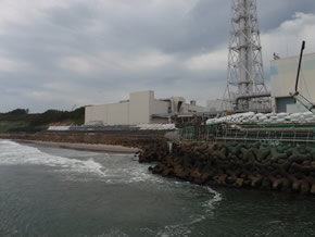
Photo 18. Temporary tide barrier
(photographed on June 30, 2011)
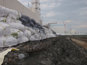
Photo 19. Temporarytide barrier
(photographed on June 30, 2011)
3) Preparation against further station deterioration
Although we have implemented countermeasures against potential earthquakes and tsunamis, as mentioned in 1) Earthquake preparations and 2) Tsunami preparations, in order to prepare for such events as multiple equipment failures or offsite power losses, we have further established redundant and diversified facilities, which can be used as back-ups.
In the event that water injection is stopped, the assumed causes will be loss of water source, damage to the water injection piping, loss of power and/or pump malfunctioning.
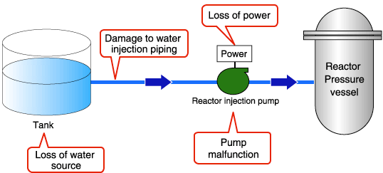
Figure 8. The assumed causes in the event that water injection is stopped
Currently, as water source, we are using a processed water buffer tank that stores processed water for reactor water injection. We also have reinforcements: filtered water tanks (2 units: 8,000 m3), pure water tanks (2 units: 2,000 m3) and a Unit 3 Condensate Storage Tank (CST) (1 unit: 2,500 m3). Backup water for the filtered water tanks can be retrieved from Sakashita dam in Okuma-town. In the event that there are no water sources available, fire engines are on standby to pump seawater as a final option. Furthermore, in preparation for water injection line damage, we built an additional water injection line with spare piping and have 3 km onsite spare hoses.
As a power source, offsite power from 5 lines are available; Okuma Lines 2 and 3, Yonomori Lines 1 and 2, and Toden Genshiryoku Line of Tohoku Electric Power Company. In the event that all lines are rendered inoperable, temporary diesel power generators dedicated to the emergency reactor injection pumps on the hill are available.
In the event of a pump failure, regular and emergency reactor injection pumps on the hill, reactor injection pumps besides the pure water tank, reactor injection pumps in the turbine building, and CST reactor injection pumps have been installed. Several onsite fire engines are also on standby.
In this way, if one of these facilities fails, following necessary preparations, we will be able to resume water injection to the reactor within 30 minutes.
In addition, if all equipment including back-up reinforcements become unavailable, fire engines will step in to resume water injection within about 3 hours.
As of October 2011 conditions, it should be noted that in the event that water injection to the reactor is stopped, further damage to the reactor core can be prevented if water injection is resumed within 18 hours.
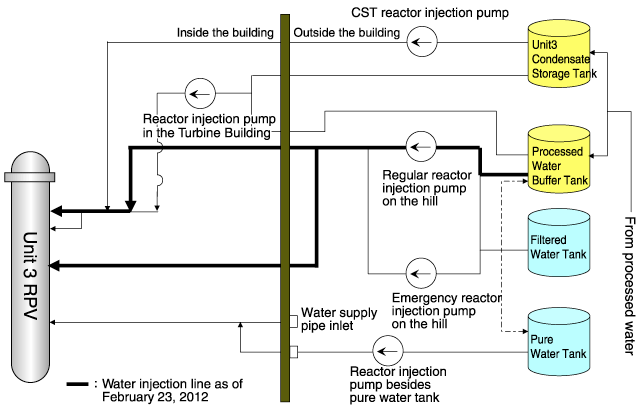
Figure 9. Outline of water injection line (example of Unit 3)
In the event that we are forced to suspend the cooling of the spent fuel pool for an extended period of time, water injection could be employed utilizing a concrete pumper as an alternative method following six hours of preparation.
As of October 2011 conditions, it should be noted that, for example at unit 4, if the cooling circulation function of the spent fuel pool stops, assessments show that it would take at least 16 days for the gap between the water surface and the Top of the Active Fuel (TAF) of the spent fuels, which is presently serving as an effective water shield, to decrease to 2 meters.
Water injection practice at Fukushima Daiichi Nuclear Power Station Oct 12, 2011![]()
(Explanation)Water and fuel status in case of a reactor water injection system malfunction
[Video] Vol.1 No.3 Reactor and Fuel Status13:50
4) Emergency response procedures
In order to convey emergency information in a prompt fashion, it is important to keep the lines of communication open from the accident site to headquarters and each municipality. At the time of the accident, various problems arose that prevented effective communication.
The normal in-house communication tools used at Fukushima Daiichi such as PHSs and fixed-line phones were rendered inoperable due to the station black out. This caused tremendous communication problems between the power station's emergency headquarters, the main control rooms and the work site. At that time, the only communication means available between the Emergency Response Center at the station and the main control rooms were fixed-line phones directly wired.
Although the existing PHS system was restored in March 2011, we installed a communication satellite system (car-loaded, portable) to provide temporary communication line support for in-house telephones, corporate local area networks and video transmissions.
In addition, in order to secure the lines of communication between related organizations such as the Fire Department, Japan Self Defense Forces and local municipalities, we installed a base transceiver station on the site.
As an emergency provision, we also prepared an extra 100 transceivers in addition to the ones provided from TEPCO's other branches after the accident.