


1.2 Urgent Response Measures
1) Utilizing every feasible method to inject water into the reactor
Due to the simultaneous and prolonged loss of all AC and DC power, the electrical operated systems were unable to inject water into the reactors of Units 1-3. It was at this stage that the fire engines were brought in. Water injection is not possible if the reactor pressure is higher than the water injection pressure from the fire engines. Therefore, at Units 2 and 3, the main steam safety relief valves (SRVs) needed to be opened to depressurize the RPV by any means. To this end, batteries were carried from the employees' cars parked in the site into the main control room and connected. The RPV pressure was decreased by opening the SRVs which allowed for water injection from the fire engines.
Additionally, while steam and hydrogen was continually released into the PCV through such equipment as the SRVs, given that heat removal operations were hampered for an extended period of time, the pressure inside the PCV rose up. To prevent damage to the PCV due to an abnormal pressure rise and the resulting uncontrollable release of radioactive materials, a decision was made to implement 'PCV venting', to reduce PCV pressure.
Figure 3. Reactor Depressurization and Water Injection
In order to conduct 'PCV venting', it is necessary to open two types of valves, a motor-operated valve and the air-operated valve. As all electric power had been lost, the station operators manually opened the motor-operated valve by turning the handle attached to the valve. Meanwhile, operators had difficulties in opening the air-operated valve manually. Hence, such equipment as air compressors (engine-operated), adaptors and batteries were required to open this valve. All of this equipment was gathered from various station locations for the 'PCV venting' operations. As the end result, we are concluding that the 'PCV venting' efforts succeeded for Units 1 and 3 as we have confirmed the PCV's pressure decrease. However, we have not confirmed that the pressure had decreased for Unit 2 by the 'PCV venting'.
Initially, freshwater from the fire protection tank was used for the fire engine water injection into the reactors. However, as freshwater ran out, sea water was injected instead. In addition, diesel fuel for the fire engine was supplied periodically to ensure continuous water injection. By the end of March 2011, temporary electric pumps were installed to inject water into Units 1-3 instead of fire engines and sufficient freshwater was prepared for water injection.
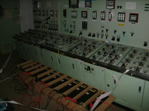
Photo 6. Temporary batteries used as power source for instruments
(photographed on March 22, 2011)
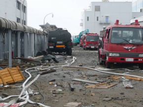
Photo 7. Water injection by fire engines
(photographed on March 16, 2011)
Fukushima Nuclear Accident Analysis Report(Interim Report) December 2, 2011![]()
*For more details, please refer to "8. Response Status after the Tsunami Attack" in this report.
Fukushima Nuclear Accident Analysis Report(Interim Report)-Summary- (December 2, 2011)![]()
Release of the interim report of Fukushima Nuclear Accidents Investigation Committee (December 2, 2011)
*Fukushima Nuclear Accident Analysis Report(Interim Report) and other relevant reports are availavle from this page.
2) Enhancing stability for reactor water injection
At first, water injection by fire engine was conducted through the pipe line (water injection route) called 'Fire Protection System (FP)' installed for emergency purposes. However, from March 2011, we were able to switch over to the 'Feed Water System (FDW)', which is normally used to cool the reactors. Furthermore, between September and December, 2011, we were able to additionally prepare the 'Core spray system (CS)' for Units 1-3. In this way, many water injection routes were prepared to enhance diversity. Furthermore, the following backup facilities were also installed in the event of equipment breakdowns, loss of off-site power, and the occurrence of another large tsunami: three regular reactor injection pumps on the hill, three emergency reactor injection pumps on the hill, three reactor injection pumps placed beside the pure water tank, six reactor injection pumps in the turbine building,and several fire engines.
The water injected into the reactor leaked out from the damaged RPV into the PCV and finally accumulated in the basement of the buildings as highly contaminated water. To prevent this water from overflowing, it was decided to transfer and store the water at the centralized radiation waste processing building which was waterproofed and remove the radioactive materials and salt from the water to be reused for reactor water injection. Hence by June 2011, we installed a "circulation water cooling system". The system consists of water processing facilities to remove salt and radioactive materials, tanks to store processed water, and other equipment such as 4 km-long pipes and hoses. In order to promptly get the system up and running, technologies were sought from all over the world to help with the installation of the water processing facilities.
Figure 4. Circulating Water Cooling System
Recovery and processing of radioactive accumulated water at Fukushima Daiichi Nuclear Power Station - Water processing facility (removal of radioactivity) – October 29, 2011 ![]()
Effort for treating radioactive accumulated water ~Outline Version~ October 22, 2011![]()
Summary of radioactive accumulated water treatment system June 9, 2011![]()
3) Cooling the spent fuel pools
To prevent the loss of cooling water due to the heat generated from the spent fuels in the spent fuel pools of Units 1-4, every measure was examined. Since the upper parts of the reactor buildings of Units 1, 3 and 4 had sustained damage due to the hydrogen explosion; a decision was made to spray water from the rooftop area of these buildings. This was done not only by employees but by the Japan Self Defense Forces using helicopters, riot police from the National Police Agency using water cannon tower vehicles, and the Tokyo Fire Department using bendable spray tower vehicles and concrete pumpers (some water cannon tower vehicles were provided by US forces). Unit 2 was injected with seawater through a pipe line called the 'Fuel Pool Cooling and Filtering System (FPC)'. Afterwards, alternative circulating cooling systems were installed that allowed for cooling without injecting water directly. Operations for this system were started for Unit 2 from March 2011, and for Units 1, 3 and 4 by August 2011.
On the other hand, from March 2011, cooling pumps were also employed to cool down the spent fuel pools of Units 5 and 6 and the common spent fuel pool in the Auxiliary Operation Shared Facility.
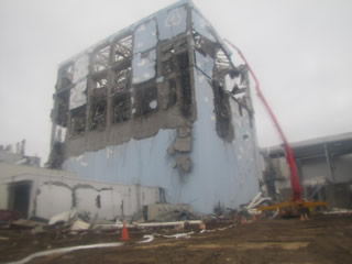
Photo 8. Water injection to Unit 4 spent fuel pool using a concrete pumper
(photographed on March 22, 2011)
<Unit 4 Building and Spent Fuel Pool Conditions>
The water temperature of Unit 4 spent fuel pool is being kept at 20-30 degrees C and the water level is 7 meters above the fuels.
Although the skimmer surge tank's water level decreased temporarily due to the January 1 2012 earthquake whose epicenter was near Torishima, the pool water temperature and the water level remained unchanged.
On February 9 2012, an underwater camera was used to verify underwater visibility. As a result, it was confirmed that the fuels stored in the pool rack had not been dislodged although some debris brought about by the building explosion remained. The presence of the debris was first confirmed via a separate inspection of the pool's inside conducted on May 7 2011.
In addition, on January 22 2012, we verified the situation on the 5th floor of the reactor building and confirmed that the water surface of the reactor well and floor level was parallel, hence it was proved that the building had not tilted.
Fukushima Nuclear Accident Analysis Report(Interim Report) December 2, 2011![]()
*For more details, please refer to "8.9 Storage status of spent fuels" in this report.
Fukushima Nuclear Accident Analysis Report(Interim Report)-Summary- (December 2, 2011)![]()
Release of the interim report of Fukushima Nuclear Accidents Investigation Committee (December 2, 2011)
*Fukushima Nuclear Accident Analysis Report(Interim Report) and other relevant reports are availavle from this page.